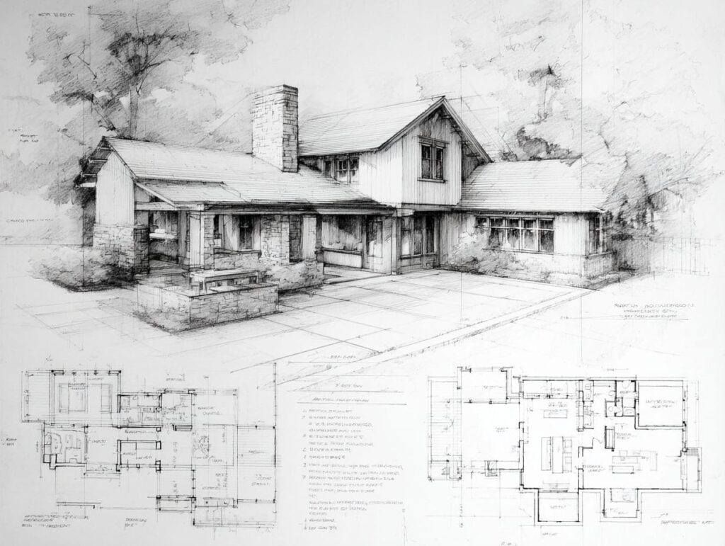
If you’re targeting Step Code 4–5, a “high-performance wall assembly” is less about piling on insulation and more about getting thermal continuity, airtightness, and moisture management right in a way trades can build consistently. The quickest path is to pick a wall strategy early, then detail the control layers (water, air, vapour, heat) through every transition as part of your custom home architectural design process.
In practical terms, Step Code 4–5 wall planning usually comes down to a few big decisions: how you reduce thermal bridging, where your primary air barrier lives, how thick the wall becomes (and what that does to windows), and how you maintain drying potential in a wet coastal climate.
At A Glance: What You’ll Lock Down Early
- A wall approach that fits your design and trades
- A single, continuous air barrier plan
- Details at openings, decks, and roof-to-wall transitions
- A rainscreen strategy that drains and dries
- Window placement that works with thicker walls
- A drawing checklist to catch missing details before you sign off
What Step Code 4–5 Changes About Wall Design
Step Code 4–5 pushes your project toward tighter construction and better overall envelope performance. That changes what matters most in your wall assembly. The wall is no longer a simple “studs plus insulation” decision. It becomes a coordinated system that has to perform at corners, connections, and penetrations.
If you want to avoid design churn, treat this as a planning problem first. You are choosing a buildable approach that your team can repeat cleanly across the whole house, not a one-off detail that looks good in one section cut.
Why “More R-Value” Is Not The Whole Story
Adding insulation can help, but it does not automatically solve the problems that make Step Code 4–5 harder. Thermal bridging through framing, rim joists, balconies, and attachments can quietly erase the gains of higher insulation values.
Airtightness also matters more than most homeowners expect. Air leakage can move heat and moisture through assemblies in ways that insulation alone cannot fix. When the home is tighter, you also rely more on intentional ventilation and controlled drying paths.
So the real goal is to build a wall that performs as a complete system: continuous layers, clear transitions, and fewer weak spots that depend on perfect caulking or “field judgement.”
The Three Levers That Move Results Most
Most Step Code 4–5 wall wins come from three levers: thermal continuity, airtightness continuity, and a window strategy that matches the wall thickness and the energy model.
Thermal continuity means you reduce bridging so heat is not escaping through the structure like a ladder. Airtightness continuity means one primary air barrier runs unbroken through the building, including the junctions that get complicated fast.
The window strategy matters because windows are high-impact components. Glazing area, placement, and installation details can change both comfort and performance. If you solve these three levers early, many other decisions become easier.
A Government Reference For Step Code Requirements
Step Code targets and adoption can vary by location and permit timing, so it’s worth checking the BC Step Code requirements as your official baseline before you lock in assumptions with your design team.
Use that page to frame the conversation, then let your energy advisor and designer translate the requirements into a buildable envelope plan. Your goal is not to memorise rules. Your goal is to make decisions early enough that drawings, pricing, and trades all align.
The Control Layers Every High-Performance Wall Needs
A high-performance wall works because it controls four things: bulk water, air, vapour and drying, and heat flow. If any one layer is unclear or discontinuous, the wall becomes fragile. It might still pass inspection, but it becomes harder to build consistently and harder to keep durable over decades.
When you review an assembly, ask a simple question: “Where is each control layer, and how does it stay continuous at edges?” If you can’t answer that from the drawings, you are relying on interpretation in the field.
Water Control Layer
The water control layer is the system that manages rain that gets past the cladding. In coastal BC, it’s smart to assume some water will get behind the exterior finish at some point. Wind-driven rain finds edges, corners, and joints.
A good water control plan focuses on openings and transitions, not the middle of the wall. If the wall works at windows, doors, and penetrations, it tends to work everywhere else. If those details are vague, the wall becomes dependent on sealants and perfect workmanship.
This is also where sequencing matters. If the water control layer is covered before it’s verified, you lose your best chance to catch continuity issues.
Air Control Layer
The air control layer is the primary defence against uncontrolled air leakage. For Step Code 4–5, you want one clear air barrier plane that trades can identify and protect. The most common failure pattern is trying to “air seal everything” without a single primary plane.
Air barrier continuity breaks at the usual suspects: slab-to-wall, rim joists, wall-to-roof, window rough openings, and service penetrations. Those transitions need specific details and clear scope assignment so nothing is “someone else’s job.”
When airtightness is planned, tested, and corrected early, you reduce the odds of chasing leaks late when fixes are expensive and disruptive.
Vapour And Drying Strategy For Coastal BC
Vapour control is not the same thing as bulk water control. Vapour is about moisture moving through materials and assemblies over time. In a wet coastal climate, you also have to think about drying potential, because assemblies can stay wet longer during long rainy seasons.
A good strategy avoids creating a “moisture trap” where the wall can get wet but cannot dry in either direction. That does not mean every assembly is risky. It means you need the right combination of materials and details for your climate, orientation, and exposure.
The simplest homeowner takeaway is this: the tighter and more insulated the wall, the more you want the moisture plan to be deliberate, not assumed.
Thermal Control Layer
The thermal control layer is your insulation strategy and how it stays continuous. In Step Code 4–5 planning, thermal performance often rises or falls at framing lines, corners, and attachments, not in the centre of the stud bays.
Continuous insulation on the exterior is a common way to reduce thermal bridging, but it brings its own detailing requirements. Deep cavity approaches can also work, but they must still manage air leakage and moisture carefully.
Whichever direction you choose, the key is that the thermal layer must remain coherent through transitions. If the insulation “falls apart” at the roofline, balconies, or window perimeters, comfort and performance suffer.
Common Step Code 4–5 Wall Assembly Approaches
There is no single “required” wall assembly for Step Code 4–5. Multiple approaches can work. The right one depends on your design intent, your cladding plan, your team’s comfort level, and what you want to prioritise: thermal bridging reduction, simpler exterior attachments, faster build sequencing, or reduced wall thickness impact.
Wall Assembly Approaches At A Glance
| Wall Approach | Where It Works Well | Watch-Outs | What To Confirm On Drawings |
| Exterior Continuous Insulation | Strong thermal continuity and reduced bridging | Cladding attachment planning, thicker assemblies, window detailing | Base-of-wall, window returns, attachment strategy, air barrier continuity |
| Double-Stud Or Deep Cavity | High insulation in cavity, fewer exterior attachment complexities | Very thick walls, window jamb depth impacts, airtightness must be deliberate | Air barrier plane, window placement, rim joist details, moisture strategy |
| Advanced Framing Plus Exterior Insulation | Balances buildability with reduced bridging | Requires disciplined framing and consistent details | Framing notes, continuity at corners, insulation continuity at transitions |
| Prefabricated High-Performance Panels | Faster enclosure, controlled shop conditions | Upfront planning and coordination, craning/logistics | Panel interfaces, air sealing at joints, sequencing and tolerances |
You can also combine approaches. What matters is that you keep the system consistent and detail the hard parts so the crew isn’t improvising.
Approach 1: Exterior Continuous Insulation Walls

Exterior continuous insulation is popular in high-performance homes because it tackles thermal bridging at the source. Instead of relying only on cavity insulation interrupted by studs, you wrap insulation around the structure to create a more continuous thermal layer.
This approach can work very well in Step Code 4–5 projects, but it rewards early planning. If you choose it late, you risk rework around windows, cladding attachments, and exterior proportions.
Why Exterior Insulation Often Performs Well
Exterior insulation can reduce heat loss through studs and structural elements, which improves thermal comfort. It can also help keep interior surfaces warmer in winter, which can reduce the conditions that lead to condensation on cold spots.
It also makes your insulation story simpler in many places. When you maintain a continuous layer outside, you reduce the number of “special cases” where details have to be perfect to avoid weak points.
The catch is that good performance depends on clean transitions. You still have to detail how the insulation and air barrier connect at corners, rooflines, and openings.
Buildability Notes For Trades And Scheduling
Exterior insulation changes how the cladding is attached and how exterior features are supported. That makes early coordination with your builder and cladding trade important. If you leave it late, you can end up with awkward fastening solutions and avoidable cost.
It also affects window detailing. Thicker walls change the relationship between the window frame, flashing, and the drainage plane. When you decide early, you can design clean jamb returns and consistent trim details instead of patching the look at the end.
From a schedule perspective, this approach benefits from having a clear sequence for air barrier work, inspections, and cladding prep. It is easier to keep momentum when the “who does what when” is written down.
What To Show On Drawings
Drawings should show how the wall drains, how the air barrier stays continuous, and how loads transfer through cladding attachments without puncturing the critical layers. It is not enough to label a wall “high-performance.” The details must show the buildable intent.
At minimum, you want clear details at the base of wall, window openings, roof-to-wall transitions, and typical penetrations. If the project includes canopies, deck ledgers, or exterior stairs, those also need a repeatable attachment detail.
A good drawing set turns this approach from “conceptually strong” into “repeatably buildable.”
Approach 2: Double-Stud Or Deep Cavity Walls

Deep cavity approaches, including double-stud walls, can achieve high insulation levels without relying on thick exterior insulation layers. They can also simplify certain exterior attachment details because the cladding fastening strategy can look more familiar to trades.
These assemblies can work well, but they come with a real architectural impact: walls get thick. That affects interior space, window returns, and the feel of the exterior detailing.
Where Deep Cavity Walls Make Sense
Deep cavity walls often suit designs where you can accommodate thicker walls without compromising the architecture. They can also be appealing when you want a more conventional-looking exterior cladding attachment approach while still achieving high insulation levels.
They can also fit projects where you want to keep the exterior layer simpler and put the insulation depth inside the structural wall zone. That can reduce some complexity around exterior insulation alignment.
The trade-off is that the wall thickness touches everything: floor area, window jamb extensions, interior trim depth, and exterior proportions.
Airtightness Strategy Is Still Required
Thicker insulation does not seal air leaks. In deep cavity walls, you still need a primary air barrier plane and a plan for transitions and penetrations. If you do not solve airtightness, you can end up with a thick wall that underperforms and carries higher moisture risk.
This is where “service planning” helps. If you can keep many penetrations out of the primary air barrier plane, you reduce the number of leak points you have to manage.
A deep cavity approach can be excellent when the airtightness strategy is simple and enforced. It becomes risky when the air barrier is implied instead of detailed.
What To Confirm Early
Window placement becomes a key design decision in thick walls. You should confirm whether windows sit closer to the exterior face, closer to the interior face, or somewhere in between, and how that affects comfort and aesthetics.
You also want to confirm how thick walls affect daylighting and views. Deep returns can create a dramatic look, but they can also reduce perceived glazing area if not planned carefully.
Finally, confirm how transitions are handled at floor lines and rim joists, because deep cavity assemblies still need clean, repeatable details at structural breaks.
Approach 3: Advanced Framing Plus Exterior Insulation

Advanced framing, sometimes called optimised value engineering or OVE framing, reduces the amount of lumber in the wall while keeping structural performance. When you pair it with a moderate layer of exterior insulation, you get a wall that balances thermal bridging reduction with a build process most framing crews already understand.
This approach does not require the thick exterior insulation layers of Approach 1 or the deep wall cavities of Approach 2. Instead, it works by making the framing itself more thermally efficient and then adding a manageable layer of continuous insulation outside to cover the remaining bridges.
Where This Approach Fits
Advanced framing plus exterior insulation tends to suit projects where you want to improve performance without dramatically changing the wall thickness or the way exterior details are handled. It can be a practical choice when your design has a lot of corners, intersecting walls, or exterior features that would become complicated with very thick insulation layers.
It also works well when your framing crew is experienced and willing to follow disciplined layouts. The approach relies on wider stud spacing, single top plates where engineering allows, right-sized headers, and elimination of unnecessary cripples and jacks. Those changes reduce wood in the wall, which means less thermal bridging through the framing itself.
The trade-off is that it requires more attention during framing layout. If the crew defaults to conventional framing habits, you lose the thermal advantage before the insulation even goes on.
Why Framing Discipline Matters More Here
In a standard wall, extra studs and doubled-up headers are common because they make the framing stage faster and simpler for the crew. In an advanced framing approach, every extra piece of lumber is a thermal bridge you chose not to eliminate.
That means framing notes on the drawings need to be specific. You want clear callouts for stud spacing, header sizing, corner details, and where single top plates are used. If the drawings just show a standard framing section and add a note that says “advanced framing,” the crew will likely frame the way they always have.
When it works, the combination of less framing and a continuous exterior insulation layer can hit Step Code 4–5 thermal targets without the wall thickness impact of deeper approaches. When framing discipline slips, the wall underperforms and the exterior insulation has to compensate for bridges it was not sized to cover.
What To Confirm On Drawings
Drawings should include specific framing notes that go beyond a typical wall section. Confirm stud spacing, header sizes, corner framing details, and where single top plates are used. The insulation layer thickness and attachment method should also be clear.
Pay attention to corners and intersecting walls, because these are the spots where advanced framing details diverge most from conventional practice. If those details are shown clearly, the crew can follow them. If they are left to interpretation, the framing usually reverts to standard practice.
You also want confirmation that the exterior insulation thickness is coordinated with the cladding attachment strategy and window placement, just as you would in Approach 1. The insulation layer may be thinner here, but the same detailing principles apply at transitions and openings.
Approach 4: Prefabricated High-Performance Panels

Prefabricated panels, including structural insulated panels and other factory-built wall systems, move much of the wall assembly work off site and into controlled shop conditions. The panels arrive with insulation, sheathing, and sometimes air barrier layers already integrated, which can compress the enclosure schedule significantly.
This approach can work very well for Step Code 4–5 when the upfront planning is thorough. The challenge is that decisions need to be locked down earlier than with stick-framed approaches, because the panels are manufactured to specific dimensions and details before they reach the site.
Where Prefabricated Panels Make Sense
Prefabricated panels suit projects where you want a faster enclosure timeline and tighter quality control over the wall assembly itself. Because the panels are built in a shop, the insulation and air barrier layers can be more consistent than what you typically get with field-installed assemblies.
They also make sense when site access or weather conditions make a long framing and sheathing phase risky. In coastal BC, getting the building enclosed quickly reduces the time the structure is exposed to rain, which helps protect moisture-sensitive materials.
The approach tends to fit projects where the design is resolved early and the owner is comfortable committing to details before panels are ordered. If the design is still changing when panels need to go into production, the costs and delays can offset the schedule advantage.
Coordination And Logistics
Prefabricated panels require more coordination between the designer, the panel manufacturer, and the site crew than most stick-framed approaches. The panel shop drawings need to align with the architectural drawings, and any discrepancies need to be caught before manufacturing, not during installation.
Site logistics also matter. Panels are usually craned into place, so you need clear access for delivery and lifting equipment. The foundation and floor structure need to be accurate to the panel tolerances, because panels do not flex to accommodate an out-of-level base the way stick framing can.
From a scheduling standpoint, the lead time for panel fabrication needs to be built into your project timeline. If you order late or make changes after production starts, the schedule advantage disappears and costs increase.
What To Confirm On Drawings And In Contracts
Drawings should show how panels connect at joints, corners, and floor lines. The air barrier continuity at panel-to-panel joints is one of the most important details, because that is where field sealing takes over from shop quality. If the joint detail is vague, air leakage at connections can undermine the performance advantage of the panels themselves.
Confirm how windows, doors, and service penetrations are handled. Some panel systems include rough openings built into the panels, while others require field cutting. The approach affects both airtightness and the sequencing of window installation.
It is also worth confirming scope boundaries in the contract. Clarity on what the panel supplier delivers versus what the site crew is responsible for, especially around air sealing at joints and connections, reduces the chance of gaps in accountability that show up during airtightness testing.
Airtightness Strategy: Where Step Code 4–5 Projects Win Or Lose
In Step Code 4–5 builds, airtightness is often the deciding factor between “we hit targets smoothly” and “we chase problems late.” It’s not only about passing a test. It’s about building an enclosure that feels consistent and comfortable, without drafts and cold spots.
The easiest way to protect airtightness is to treat it like a design layer, not a jobsite afterthought. Decide what your primary air barrier is, then detail its continuity through every common break.
Choose The Primary Air Barrier And Protect It
Pick one primary air barrier plane and make it obvious. Trades should be able to point to it and understand how to keep it continuous. When you have multiple partial air barriers, you often end up with gaps between them that are hard to see and harder to fix.
Protection matters. The air barrier layer gets compromised most often during rough-ins and late changes. If you plan service routes and penetrations early, you reduce the number of holes that need patching and taping later.
This is also where scope clarity helps. When the air barrier responsibilities are clear, the quality stays consistent.
Continuity At Transitions
Transitions are where airtightness fails. Slab-to-wall, wall-to-roof, window rough openings, and service penetrations need details that show exactly how the air barrier connects.
A practical way to think about it is “draw the line.” If you can draw a single line around the building on your details without lifting your pen, you are closer to a buildable airtightness plan.
If you can’t draw the line, that does not mean the project is impossible. It means you need more detail before the crew is asked to execute it.
Plan For Testing And Fixes Without Panic
Airtightness testing is useful because it gives you feedback while fixes are still possible. The worst-case scenario is waiting until the project is too far along to fix issues without opening finished work.
The best approach is to plan testing as a checkpoint and include time to address findings. That keeps fixes calm and controlled, instead of rushed and expensive.
For homeowners, it also provides confidence that performance is being verified, not guessed.
Thermal Bridging Hot Spots To Detail Early
Thermal bridging is often invisible in drawings and obvious in real life. You feel it as cold corners, uneven floors near edges, and comfort differences between rooms. In Step Code 4–5 planning, you want to target the common hot spots early because they repeat across the house.
Think of thermal bridging as a design debt. If you ignore it in early details, it shows up later as comfort complaints and performance shortfalls.
Corners, Rim Joists, And Floor Lines
Corners and rim joists are classic weak points because structure and geometry get complicated. You often have multiple framing members converging, plus a change in direction that makes insulation continuity harder.
Floor lines can also create repeating bridges if the insulation strategy changes at each level. A good high-performance detail treats floor lines as continuity problems to solve once, then repeat.
From a drawing standpoint, you want typical details that show how insulation and air barrier layers remain continuous at these repeating conditions.
Cantilevers, Deck Connections, And Exterior Features
Cantilevers and deck connections can punch through thermal layers and create major bridges. Exterior features like canopies, brackets, and exterior stairs can do the same thing if they are attached without a plan.
This is where “designing the attachments” matters. If you plan where loads transfer and how penetrations are sealed, you can keep performance intact without giving up outdoor living.
If you don’t plan it, the crew will choose the simplest structural solution in the field, and that solution often creates the biggest bridge.
Roof-To-Wall Continuity
The roof-to-wall junction is where insulation and air barrier continuity gets tested. Complex rooflines, multiple valleys, and changes in ceiling height can make it easy to lose the continuity story.
How you handle roof assemblies for West Coast climate conditions directly affects how well the wall-to-roof transition performs.
Even if your roof design is straightforward, the roof-to-wall detail deserves special attention because it is a high-impact transition that is hard to fix after the fact.
Moisture Management And Drying Potential In Coastal BC

High-performance walls can be thicker and tighter, which is great for comfort and energy use. It also means moisture planning needs to be deliberate. In coastal BC, the key is not to fear high-performance walls. It’s to detail them so they can manage wetting events and still dry.
Your wall assembly should assume real life: wind-driven rain, seasonal debris, and the fact that penetrations happen. The best assemblies are resilient to those realities.
Why Rainscreens Still Matter On High-Performance Walls
A rainscreen provides a drainage and drying space behind cladding. Even on high-performance walls, that space helps manage the moisture load that comes with coastal conditions. It’s one of the most reliable durability upgrades you can plan into a wall assembly here.
Understanding the rainscreen requirements for coastal BC homes helps clarify how drainage gaps, terminations, and sequencing affect your wall assembly drawings.
The main planning takeaway is that rainscreens affect wall thickness, window detailing, and cladding attachments. If you decide them late, you tend to redesign.
Terminations, Flashings, And Penetrations
Most moisture problems show up at edges: windows, doors, deck connections, and service penetrations. That’s where water concentrates and where multiple trades touch the same detail.
The simplest risk reduction strategy is to minimise penetrations, group them where you can, and use repeatable details that everyone understands. When details vary from one location to another, quality tends to vary too.
Good drawings don’t just show the wall. They show how the wall ends, drains, and survives penetrations.
Windows And Glazing: The Step Code Connection Homeowners Miss
Windows are often chosen for looks first, then “made to work” later. In Step Code 4–5 projects, that approach can create performance and detailing stress. Thicker walls and higher targets mean window placement and glazing decisions have more impact.
This does not mean you need tiny windows. It means you want the window strategy and wall strategy to be designed together.
Window Placement In Thick Walls
Thicker walls create deeper returns and change where a window sits relative to the insulation and drainage plane. That affects comfort at the window, condensation risk, and the look of both interior trim and exterior details.
When you decide window placement early, you get consistent details. You can also avoid the common “last-minute jamb extension” look that feels bulky and inconsistent across rooms.
A practical way to think about it is this: the wall tells you where the best window location is, not the other way around.
Window-To-Wall Ratio Affects Energy Modelling
Even if you love glass, glazing area and orientation can change how difficult it is to hit Step Code targets. More glazing can increase heat loss and can push other parts of the enclosure to work harder to compensate.
Balancing glazing area with energy performance is easier when you understand how window-to-wall ratio and daylighting interact in the energy model.
The goal is a window plan that supports comfort, views, and performance, without forcing awkward wall thickness or costly detailing solutions.
What To Look For In Drawings Before You Approve The Set
High-performance outcomes depend on drawings that make the important things easy to build. If critical details are missing, they get improvised. Improvisation is where performance gets lost, especially at Step Code 4–5.
Your review doesn’t need to be technical. It needs to be targeted. Focus on transitions, penetrations, and anything that repeats across the house.
The “If It’s Not On The Drawings, It’s Not Real” Rule
A high-performance wall assembly is not real unless the drawings show how it’s built at the hard parts. Labels and notes are not enough. You need details that show continuity of the control layers, especially at the base of wall, windows, roof-to-wall, and deck or canopy connections.
This matters because trades are working quickly. When details are clear, the work is repeatable. When details are vague, the result varies by crew, and performance becomes inconsistent.
A useful sign that the set is ready is when your builder can price it confidently and your trades can understand the sequencing without a long debate.
A Homeowner Review Checklist
If you want a simple way to review your set, look for these items before you approve: a defined primary air barrier plane, continuity at roof-to-wall and slab-to-wall transitions, clear window installation details, a cladding attachment concept, and a repeatable penetration detail.
Knowing how to review architectural drawings with a control-layer focus helps you catch missing details before they become field problems.
That review step is where many Step Code projects prevent rework. It’s easier to fix a missing detail on paper than on a finished wall.
Step Code 4–5 Wall Assembly Planning Checklist
A checklist helps keep the wall assembly decision from drifting. It also helps you spot when the project is trying to move forward without the details needed to protect performance.
Use this list as a design meeting agenda. If your team can answer these items clearly, you’re usually in a good place to move into permits and trade pricing.
- Confirm the target Step Code level and the overall performance approach with your energy advisor
- Choose a primary wall strategy (exterior insulation, deep cavity, or another approach)
- Define the primary air barrier plane and who owns each transition
- Detail slab-to-wall, wall-to-roof, and window rough opening transitions early
- Confirm a rainscreen strategy that drains and dries in coastal conditions
- Confirm window placement in thick walls and how it affects interior returns and exterior expression
- Decide the cladding attachment concept and document it clearly
- Group and minimise penetrations where feasible, with repeatable details
- Plan exterior attachments (decks, canopies, railings) so they don’t undermine thermal continuity
- Identify construction checkpoints where continuity can be inspected before it’s covered
- Plan testing and remediation time so fixes stay calm and controlled
- Review the drawing set with a “control layers” lens before signoff
If you treat this as a one-time exercise, you reduce the chance that the wall assembly gets value-engineered or compromised by late changes.
How Versa Homes Helps You Build Step Code Wall Details Without Rework
Step Code 4–5 wall assemblies work best when they’re treated as a coordinated system, not a collection of upgrades. When you decide the wall approach early and document the control layers clearly, you reduce redesign cycles, protect long-term durability, and make pricing and scheduling more predictable.
We support that process with fixed-price contracts once scope is defined, a detailed build schedule with pre-booked trades, and a client portal that keeps drawings, selections, and progress photos organised with daily logs. If you’re planning a Step Code home in Greater Vancouver, our architectural design services can help you lock down a buildable wall strategy early, before the project hits permits and rough-ins.
Frequently Asked Questions
Do Step Code 4–5 Homes Require A Specific Wall Assembly?
No. Step Code performance targets can be met with different wall approaches. The key is choosing an assembly that controls thermal bridging, airtightness, and moisture with details your trades can build consistently.
Is Exterior Continuous Insulation Better Than Double-Stud Walls?
Not always. Exterior insulation often reduces thermal bridging more directly, while double-stud or deep cavity walls can simplify some exterior attachment details. The better choice depends on your design, wall thickness tolerance, cladding strategy, and your team’s comfort with the details.
How Thick Do Walls Get At Step Code 4–5?
Walls are often thicker than standard construction, and that affects window returns, exterior trim depth, and sometimes interior space. Plan wall thickness before you finalise elevations and window packages so the architecture stays cohesive.
What Is The Biggest Cause Of Missed Performance Targets?
Most misses come from discontinuities at transitions, not from the middle of the wall. Roof-to-wall junctions, window openings, rim joists, and penetrations are common weak points when details are missing or inconsistent.
Do High-Performance Walls Increase Moisture Risk In Coastal BC?
They can if drying potential is ignored or if water control details are vague at openings and terminations. A clear rainscreen strategy and well-detailed transitions help manage coastal moisture conditions.
Do I Still Need A Rainscreen With A High-Performance Wall?
In coastal BC, rainscreens are widely treated as a durability baseline because they help walls drain and dry. Confirm your project-specific expectations with your municipality and design team, and make sure the details are shown clearly in drawings.
What Details Should Be Included In A Permit Set For These Walls?
At minimum, include typical details at base of wall, window and door openings, roof-to-wall transitions, and common penetrations. These details should show the continuity of control layers and avoid leaving key decisions to the field.
How Can I Review Drawings If I’m Not Technical?
Use a control-layer checklist and focus on transitions first. If you can’t identify where the air barrier runs, how the wall drains at openings, or how attachments are handled, ask for those details before you approve the set.


Felipe Freig
Founder of Versa Homes
Felipe Freig is the founder of Versa Homes, a Vancouver custom home builder known for architecturally driven, fixed-price projects. With years of hands-on site experience and deep permitting and by-law knowledge, Felipe leads high-performance teams that deliver precision craftsmanship, clear budgets, and on-schedule luxury homes.
You May Also Like...


The Final Touches: Explore Exquisite Finishing Details for Your Custom Home

The Cost of Building a Custom Home vs. a Spec Home

BCBC Part 9 Spatial Separation: A Guide For Custom Homes

Architect, Builder, And Engineer: Who Is Responsible For What?

When Do You Need A Geotechnical Report For A Custom Home Lot?

What Should a Builder Charge to Build a Custom Home